Version: OpendTect 6.0
It is sometimes the case that an important reflection event we can see in 3D seismic data is not actually trackable due to inconsistent geology or poor data quality. We can still get a surface out of the data through the manual tracking workflow below. Note this does
not use the Manual Tracking mode available on the Mode tab. By using the Auto-track mode we can make use of the v hotkey to make the horizon/seeds/surface visible in full or only at sections, a very handy feature the Manual Tracking mode does not have.
- Create new horizon with Mode tab: Section Auto-track, Event tab: Allowed difference (%) = 1, Correlation tab: Correlation threshold (%) = 99. This effectively shuts down tracking away from seed points, just leaving the seeds (Fig. 1). The example given here is the seismic unconformity between Middle and Lower Fayetteville SH in the Desoto 3D seismic survey of NE Conway County, AR (data credit: SWN).
- Pick the horizon on, say, every 10th line to make a point cloud, then right-click on the horizon name to choose Tools > Gridding ... creating a grid (Fig. 3)
- Usually a good idea to smooth the grid (Tools > Filtering ...) as in Fig. 4 where a 7x7 bin smoothing has been applied.
- Once a smooth grid is obtained, add contours in the usual way (Fig. 5).
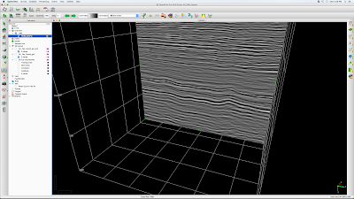 |
| Fig. 1 Crossline 1685 PSTM data showing subtle unconformity a bit below 500 ms. |
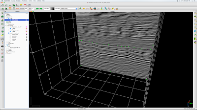 |
| Figure 2. Seeds manually picked along the unconformity. |
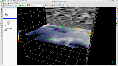 |
| Figure 3. Seeds picked on every 10th cross line and gridded. |
 |
| Figure 4. Gridded unconformity surface after 7x7 bin smoothing |
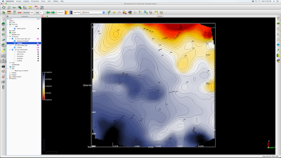 |
| Figure 5. Unconformity horizon time structure with contours. |
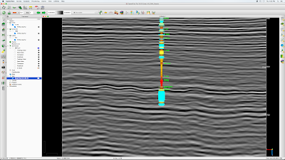 |
| Bryant Coy well with deflection as velocity and colored by gamma ray, showing subtle unconformity at M/L Fayetteville interface. |


